IP Addressing: NAT Configuration Guide, Cisco IOS Release 15M&T
The documentation set for this product strives to use bias-free language. For the purposes of this documentation set, bias-free is defined as language that does not imply discrimination based on age, disability, gender, racial identity, ethnic identity, sexual orientation, socioeconomic status, and intersectionality. Exceptions may be present in the documentation due to language that is hardcoded in the user interfaces of the product software, language used based on RFP documentation, or language that is used by a referenced third-party product. Learn more about how Cisco is using Inclusive Language.
Book Title
IP Addressing: NAT Configuration Guide, Cisco IOS Release 15M&T
NAT Box-to-Box High-Availability Support
View with Adobe Reader on a variety of devices
Results
Chapter: NAT Box-to-Box High-Availability Support
NAT Box-to-Box High-Availability Support
The NAT Box-to-Box High-Availability Support feature enables network-wide protection by making an IP network more resilient to potential link and router failures at the Network Address Translation (NAT) border.
NAT box-to-box high-availability functionality is achieved when you configure two NAT translators that reside across different devices as part of a redundancy group (RG) and function as a translation group. One member of the translation group acts as an active translator and the other member in the group acts as a standby translator. The standby translator takes over as the active translator in the event of any failures to the current active translator.
This module provides information about NAT box-to-box high-availability support and describes how to configure this feature.
Finding Feature Information
Your software release may not support all the features documented in this module. For the latest caveats and feature information, see Bug Search Tool and the release notes for your platform and software release. To find information about the features documented in this module, and to see a list of the releases in which each feature is supported, see the feature information table.
Use Cisco Feature Navigator to find information about platform support and Cisco software image support. To access Cisco Feature Navigator, go to https://cfnng.cisco.com/. An account on Cisco.com is not required.
Prerequisites for NAT Box-to-Box High-Availability Support
Network Address Translation (NAT)-related configurations must be manually configured and the configuration must be identical on both devices, and associated to the same redundancy group (RG).
RG must be shut down on both peer devices before you configure NAT.
If devices are already in active/standby states, you must apply any additional configuration changes first on the standby device and then on the active device. To delete NAT configuration rules, you must apply the changes first on the active device and then on the standby device.
Restrictions for NAT Box-to-Box High-Availability Support
We recommend that you disable all other ALGs using the no ip nat service command, when using this feature.
Information About NAT Box-to-Box High-Availability Support
NAT Box-to-Box High-Availability Overview
The NAT Box-to-Box High-Availability Support feature enables network-wide protection by making an IP network resilient to potential link and router failures at the Network Address Translation (NAT) border.
The NAT Box-to-Box High-Availability Support feature leverages services provided by the redundancy group (RG) infrastructure present on the device to implement the high-availability functionality. The RG infrastructure defines multiple RGs to which applications can subscribe to and function in an active-standby mode across different devices. NAT box-to-box high-availability functionality is achieved when you configure two NAT translators, residing across different devices, to an RG and function as a translation group. One member of the translation group acts as an active translator and the other members of the translation group acts as a standby translator. The active translator is responsible for handling traffic that requires address translation. Additionally, the active translator informs the standby translator about packet flows that are being translated. The standby translator uses this information to create a duplicate translation database that equips the standby translator to take over as the active translator in the event of any failures to the active translator. Therefore, the application traffic flow continues unaffected as the translations tables are backed up in a stateful manner across the active and standby translators.
The NAT Box-to-Box High-Availability Support feature supports active-standby high-availability failover and asymmetric routing. The NAT Box-to-Box High-Availability Support feature supports the following NAT features:
Simple Static NAT configuration
Extended Static NAT configuration
Network Static NAT configuration
Dynamic NAT and Port Address Translation (PAT) configuration
NAT inside source, outside source, and inside destination rules
NAT rules for Virtual Routing and Forwarding (VRF) instances to IP
NAT rules for VRF-VRF (within same VRF)
Reasons for Active Device Failover
The following are some of the reasons for the failover of an active device:
Power loss or reload on the active device.
Control interface for the redundancy group (RG) is shut down or the link to the interface is down.
Data interface for the RG is shut down or the link to the interface is down.
Tracked object failure.
Protocol keepalive failure.
The run-time priority of the active device is below the configured threshold. Run-time priority can go down in the following scenarios:
Traffic interface, that is assigned a Redundancy Interface Identifier (RII) value, is down.
Object tracked by the RG is down.
RG on an active device is reloaded using the redundancy application reload group command in privileged EXEC mode.
RG on an active device is shut down using the group command in redundancy application configuration mode.
NAT in Active-Standby Mode
In active-standby mode, the redundancy group (RG) that Network Address Translation (NAT) is part of remains in the standby mode on one device and active on a peer device. NAT in an RG that is in active mode translates the traffic according the configured translation rules.
NAT does not actively perform any translations on the device where its RG is in the standby mode. In an RG, only one peer is in active mode at a given instance and the other peer is in standby mode. Applications that belong to the RG are active only on the device on which the RG is active. On all other devices, applications that belong to the RG are in the standby mode.
| Note | In a group of RG peers, only one peer can be active for a specific RG. Currently, the NAT Box-to-Box High-Availability Support feature supports only two peers in an RG and one RG in the RG infrastructure. |
NAT Box-to-Box High-Availability Operation
The following figure illustrates the NAT box-to-box high-availability operation in a LAN-LAN topology. The green color represents an active device and the yellow color represents a standby device.
Figure 1. NAT Box-to-Box High Availability Operation 
NAT Box-to-Box High-Availability LAN-LAN Topology
In a LAN-LAN topology, all participating devices are connected to each other through LAN interfaces on both the inside and the outside. The figure below shows the NAT box-to-box LAN-LAN topology. Network Address Translation (NAT) is in the active-standby mode and the peers are in one redundancy group (RG). All traffic or a subset of this traffic undergoes NAT translation.
| Note | Failover is caused by only those failures that the RG infrastructure listens to. |
Figure 2. NAT Box-to-Box High-Availability LAN-LAN Topology 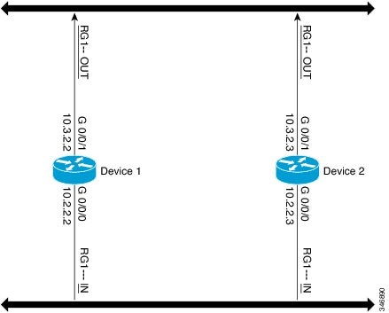
NAT Box-to-Box High-Availability WAN-LAN Topology
In a WAN-LAN topology, two devices are connected through LAN interfaces on the inside and WAN interfaces on the outside. There is no control on the routing of return traffic received through WAN links. In most cases, WAN links are provided by different service providers. To utilize WAN links to the maximum, configure an external device to provide a failover.
In the following figure, inside interfaces are connected to a LAN while outside interfaces are connected to a WAN. The WAN interfaces cannot be made part of a redundancy group (RG) according to the current RG infrastructure. However, WAN interfaces may be configured in such a way that any failure on the WAN interfaces reduces the priority for the RG that is configured on that node, thereby triggering a failover.
Figure 3. NAT Box-to-Box High-Availability WAN-LAN Topology 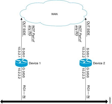
Exclusive Virtual IP Addresses and Exclusive Virtual MAC Addresses
Virtual IP (VIP) addresses and virtual MAC (VMAC) addresses are used by security applications to control interfaces that receive traffic. An interface is paired with another interface, and these interfaces are associated with the same redundancy group (RG). The interface that is associated with an active RG exclusively owns the VIP and VMAC addresses.
The Address Resolution Protocol (ARP) process on the active device sends ARP replies for any ARP request for the VIP, and the Ethernet controller for the interface is programmed to receive packets destined for the VMAC.
When an RG failover occurs, the ownership of the VIP and VMAC changes. The interface that is associated with the newly active RG sends a gratuitous ARP message and programs the interface’s Ethernet controller to accept packets destined for the VMAC.
NAT Asymmetric Routing
In asymmetric routing, packets of a single connection or session flow through different routes in the forward and reverse directions. Asymmetric routing could occur due to link failures in the network, load balancing, a specific network configuration, and so on. Network Address Translation (NAT) provides session termination services and the associated dynamic session information. For NAT, if the return TCP segments are not forwarded to the same device that receives the initial synchronization (SYN) segment, the packet is dropped because it does not belong to any known session.
NAT Box-to-Box High Availability on Asymmetric-Routing Topology
The following figure shows asymmetrically routed packets being received on a standby device: Figure 4. NAT Box-to-Box High Availability on Asymmetric-Routing Topology 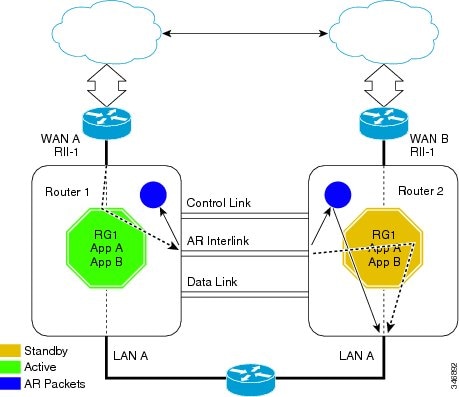
Each routing device has an asymmetric routing (AR) module, which forwards the traffic received by the standby redundancy group (RG) using the module’s AR interface. In the above illustration, the standby RG is RG1, on Router 1 with the Redundancy Interface Identifier (RII) configured as RII-1. The packet traffic that is received by RG1 is forwarded over the AR interface configured on Router 1 towards Router 2. This traffic is received by the AR module for RII-1 on Router 2 and is forwarded to RG1, which is active on Router 2.
Disabling NAT High Availability on Asymmetric-Routing Topology
When a packet ingresses Router 1 through the Redundancy Interface Identifier (RII), RII-1, Network Address Translation (NAT) identifies that packet as belonging to redundancy group (RG) RG1, which is in the standby state. If the asymmetric routing support is disabled, packets are not redirected to the active device by the standby device. Therefore, packets are dropped by default on the standby peer device.
Key Configuration Elements for NAT Box-to-Box High Availability Support
Redundancy group (RG) Asymmetric Routing (AR) interface: A dedicated physical interface that provides connectivity between two peer devices. The redundancy infrastructure uses this interface to redirect AR packets from a standby device to an active device. The AR, control, and data interfaces can be configured on the same physical interface.
Redundancy number: A unique identification number for each interface that is part of the RG infrastructure.
RG priority: A numeric value that you can configure on the active or standby devices to control the switchover behavior. Each potential fault or error decrements the priority of the active device. The system switches over to the standby device when the priority value reaches the configured limit.
RG control interface: A dedicated physical interface that provides connectivity between the two peer devices. The redundancy infrastructure uses this interface to exchange control information between the devices.
RG data interface: A dedicated physical interface that provides connectivity between two peer devices. This interface is used by the redundancy infrastructure for data information exchange between devices, such as session information for NAT. Control and data interfaces can be configured on the same physical interface.
Virtual IP address and virtual MAC address: The active device owns the virtual IP address and the virtual MAC address. Hosts or servers on the LAN that use the virtual IP address to reach the device which is currently in RG active state.
RG decrement number: The priority value of an RG in local peer is decremented by the specified priority decrement number if the interface on which this configuration is applied goes down.
RG infrastructure: Defines multiple RGs to which applications can subscribe and function in an active-standby mode across different routing devices. Currently, Network Address Translation (NAT) supports only one RG with an RG ID value of either 1 or 2.
NAT mapping ID: A numeric value that is attached to all NAT rules that are associated to an RG. This value must be unique across different NAT rules and must be the same across NAT configurations on active and standby devices.
How to Configure NAT Box-to-Box High-Availability Support
Perform configurations listed in this section on both the active and standby devices.
The redundancy group (RG) ID must be the same for both devices.
A unique redundancy interface identifier (RII) must be configured for each interface on a device that is part of the RG infrastructure.
An RG ID and virtual IP address must be configured on each interface on a LAN.
An RG ID and mapping ID must be configured for each Network Address Translation (NAT) statement.
After configuring all NAT statements, you must enable RG.
Configuring a Redundancy Application Group
SUMMARY STEPS
- enable
- configure terminal
- redundancy
- application redundancy
- group id
- name group-name
- shutdown
- priority value [ failover threshold value ]
- preempt
- track object-number
- end
DETAILED STEPS
Example:
Enables privileged EXEC mode.
Enter your password if prompted.
Example:
Enters global configuration mode.
Example:
Enters redundancy configuration mode.
Example:
Enters redundancy application configuration mode.
Example:
Enters redundancy application group configuration mode.
Example:
(Optional) Specifies an optional alias for the protocol instance.
Example:
(Optional) Shuts down a redundancy group manually.
priority value [ failover threshold value ]
Example:
(Optional) Specifies the initial priority and failover threshold for a redundancy group.
Example:
Enables preemption on the group and enables the standby device to preempt the active device regardless of the priority.
Example:
Specifies the priority value of a redundancy group that will be decremented if an event occurs.
Example:
Exits redundancy application group configuration mode and enters privileged EXEC mode.
Configuring Data, Control, and Asymmetric Routing Interfaces
The interface that is used as the control interface.
The interface that is used as the data interface.
The interface that is used for asymmetric routing. This is an optional task. Perform this task only if you are configuring asymmetric routing for Network Address Translation (NAT).
Asymmetric routing, data, and control must be configured on separate interfaces.
SUMMARY STEPS
- enable
- configure terminal
- redundancy
- application redundancy
- group id
- data interface-type interface-number
- control interface-type interface-number protocol id
- timers delay seconds [ reload seconds ]
- asymmetric-routing interface type number
- asymmetric-routing always-divert enable
- end
DETAILED STEPS
Example:
Enter your password if prompted.
Example:
Enters global configuration mode.
Example:
Enters redundancy configuration mode.
Example:
Configures application redundancy and enters redundancy application configuration mode.
Example:
Configures a redundancy group (RG) and enters redundancy application group configuration mode.
data interface-type interface-number
Example:
Specifies the data interface that is used by the RG.
control interface-type interface-number protocol id
Example:
The control interface is also associated with an instance of the control interface protocol.
timers delay seconds [ reload seconds ]
Example:
Specifies the time required for an RG to delay role negotiations that start after a fault occurs or the system is reloaded.
asymmetric-routing interface type number
Example:
Specifies the asymmetric routing interface that is used by the RG.
asymmetric-routing always-divert enable
Example:
Always diverts packets received from the standby RG to the active RG.
Example:
Exits redundancy application group configuration mode and enters privileged EXEC mode.
Enabling Data, Control and Asymmetric Routing Interfaces
SUMMARY STEPS
- enable
- configure terminal
- interface type number
- ip address ip-address mask
- no shutdown
- exit
- interface type number
- ip address ip-address mask
- no shutdown
- exit
- interface type number
- ip address ip-address mask
- no shutdown
- exit
DETAILED STEPS
Example:
Enter your password if prompted.
Example:
Enters global configuration mode.
interface type number
Example:
Enters interface configuration mode for the data interface.
ip address ip-address mask
Example:
Assigns an IP address for the data interface.
Example:
Enables the interface.
Example:
Exits interface configuration mode and enters global configuration mode.
interface type number
Example:
Enters interface configuration mode for the control interface.
ip address ip-address mask
Example:
Assigns an IP address to the control interface.
Example:
Enables the interface.
Example:
Exits interface configuration mode and enters global configuration mode.
interface type number
Example:
(Optional) Enters interface configuration mode for the asymmetric routing (AR) interface.
ip address ip-address mask
Example:
(Optional) Assigns an IP address to the AR interface.
Example:
(Optional) Enables the interface.
Example:
(Optional) Exits interface configuration mode and enters global configuration mode.
Configuring NAT Box-to-Box Interface Redundancy
Perform this task on the active and standby devices in the redundancy group to configure the Network Address Translation (NAT) box-to-box high-availability support.
SUMMARY STEPS
- enable
- configure terminal
- interface type number
- ip address ip-address mask
- ip nat inside
- redundancy rii id
- redundancy group id ip virtual-ip [ exclusive ] [ decrement value ]
- exit
- interface type number
- ip address ip-address mask
- ip nat outside
- redundancy rii id [ decrement number ]
- redundancy group id ip virtual-ip [ exclusive ] [ decrement value ]
- exit
- ip nat inside source static local-ip global-ip [ redundancy rg-id mapping-id map-id ]
- end
DETAILED STEPS
Example:
Enables privileged EXEC mode.
Enter your password if prompted.
Example:
Enters global configuration mode.
interface type number
Example:
Configures an interface and enters interface configuration mode.
ip address ip-address mask
Example:
Assigns a virtual IP (VIP) address on the interface.
Example:
Designates that traffic originating from the interface is subject to Network Address Translation (NAT).
redundancy rii id
Example:
Configures a Redundancy Interface Identifier (RII) for redundancy group-protected traffic interfaces.
redundancy group id ip virtual-ip [ exclusive ] [ decrement value ]
Example:
Enables the redundancy group (RG) traffic interface configuration.
Example:
Exits interface configuration mode and enters global configuration mode.
interface type number
Example:
Configures an interface and enters interface configuration mode.
ip address ip-address mask
Example:
Assigns a virtual IP (VIP) address on the interface.
Example:
Designates that traffic destined for the interface is subject to NAT.
redundancy rii id [ decrement number ]
Example:
Configures an RII for redundancy group-protected traffic interfaces.
redundancy group id ip virtual-ip [ exclusive ] [ decrement value ]
Example:
Enables the redundancy group (RG) traffic interface configuration and specifies the decrement value number that is decremented from the priority when the state of the interface goes down.
Example:
Exits interface configuration mode and enters global configuration mode.
ip nat inside source static local-ip global-ip [ redundancy rg-id mapping-id map-id ]
Example:
Enables NAT redundancy of the inside source and associates the mapping ID to NAT high-availability redundancy.
Example:
Exits interface configuration mode and enters privileged EXEC mode.
Configuring Asymmetric Routing for NAT Box-to-Box High-Availability Support
Perform this task on the active and standby devices in the redundancy group to configure asymmetric routing support on Network Address Translation (NAT) Box-to-Box high availability.
SUMMARY STEPS
- enable
- configure terminal
- interface type number
- ip address ip-address mask
- ip nat outside
- redundancy rii id [ decrement number ]
- redundancy asymmetric routing enable
- exit
- ip nat inside source static local-ip global-ip [ redundancy RG-id mapping-id map-id ]
- end
DETAILED STEPS
Example:
Enables privileged EXEC mode.
Enter your password if prompted.
Example:
Enters global configuration mode.
interface type number
Example:
Configures an interface and enters interface configuration mode.
ip address ip-address mask
Example:
Assigns a virtual IP (VIP) address on the interface.
Example:
Designates that traffic destined for the interface is subject to Network Address Translation (NAT).
redundancy rii id [ decrement number ]
Example:
Configures a Redundancy Interface Identifier (RII) for redundancy group-protected traffic interfaces.
redundancy asymmetric routing enable
Example:
Establishes an asymmetric flow diversion tunnel for each redundancy group (RG).
Example:
Exits interface configuration mode and enters global configuration mode.
ip nat inside source static local-ip global-ip [ redundancy RG-id mapping-id map-id ]
Example:
Enables NAT redundancy of the inside source and associates the mapping ID to NAT high-availability redundancy.
Example:
Exits interface configuration mode and enters privileged EXEC mode.
Configuration Examples for NAT Box-to-Box High-Availability Support
Example: Configuring a Redundancy Application Group
The following example shows how to configure a redundancy group named group1 with priority and preempt attributes:
Example: Configuring Data, Control, and Asymmetric Routing Interfaces
Example: Enabling Data, Control and Asymmetric Routing Interfaces
Example: Configuring a NAT Box-to-Box High-Availability Support
Example: Configuring Asymmetric Routing for NAT Box-to-Box High-Availability Support
Additional References for NAT Box-to-Box High-Availability Support
Related Documents
Cisco IOS commands
Technical Assistance
The Cisco Support and Documentation website provides online resources to download documentation, software, and tools. Use these resources to install and configure the software and to troubleshoot and resolve technical issues with Cisco products and technologies. Access to most tools on the Cisco Support and Documentation website requires a Cisco.com user ID and password.
Feature Information for NAT Box-to-Box High-Availability Support
The following table provides release information about the feature or features described in this module. This table lists only the software release that introduced support for a given feature in a given software release train. Unless noted otherwise, subsequent releases of that software release train also support that feature.
Feature Configuration Information
NAT Box-to-Box High Availability Support
NAT Box-to-Box High-Availability Support feature makes an IP network more resilient to potential link and routing device failures at the Network Address Translation (NAT) border.
NAT box-to-box high-availability functionality is achieved when you configure two NAT translators that reside across different devices as part of a redundancy group (RG) and function as a translation group. One member of the translation group acts as an active translator and the other member in the group acts as a standby translator. The standby translator takes over as the active translator in the event of any failures to the current active translator.
The following commands were introduced or modified: ip nat inside source , ip nat outside source , show ip nat redundancy , show ip nat translations redundancy , show redundancy application group .
Что это такое IPV6 и IPV4
Многие из пользователей довольно часто сталкиваются с терминами «IP», «IPv4», «IPv6», «IPng», меняют IP-настройки своего компьютера, обсуждают специфику динамического и статического IP-адреса, и при этом часто не до конца владеют смысловой нагрузкой данных слов. А ведь современный интернет построен на действии интернет-протокола (IP) и его вариаций, по правилам которых передаётся и принимается нужная нам информация. В этом материале я расскажу, что это такое IPV6 и IPV4, опишу специфику их функционала и характерные особенности.

Что такое IP
Прежде чем начать рассказ о том, что это IPv6 и IPv4, следует обозначить, что же значит сам термин «IP».
IP (сокращённое от Internet Protocol – Интернет Протокол) – это маршрутизируемый сетевой протокол, который устанавливает технический формат пакетов и схему адресации для компьютеров, обменивающихся друг с другом информацией через сеть. Большинство сетей объединяют IP с протоколом более высокого уровня, называемым TCP (Transmission Control Protocol – Протокол управления передачей), который создаёт виртуальное соединение между начальным пунктом и пунктом назначения.

IP можно легко сравнить с почтовой системой. IP позволяет адресовать пакеты и отправлять их в систему, но не существует прямой связи между отправителем и получателем. TCP/IP же позволяет создавать соединение между хостами так, что они могут обмениваться сообщениями за определённый промежуток времени.
IPV6 и IPV4 — специфика функционала
Ныне существуют две версии Интернет Протокола (IP) – IPv4 (IP версия 4) и более новая версия, называя IPv6 (IP версия 6). IPv6 является следующей эволюционной ступенью в развитии IP, и ещё некоторое время будет сосуществовать параллельно с более старой версией IPv4. В ответе на вопрос, что значит IPv6 и IPv4 более подробно остановимся на каждом из них.
Что такое IPv4
IPv4 (Интернет Протокол версии 4) является четвёртой версией Интернет Протокола (IP), и используется для идентификации устройств в сети через адресную систему, позволяя, так же, соединять устройства через веб.

IPv4 использует 32-битную адресную схему, позволяя существование 2^32 (более 4 миллиардов) адресов. При этом вместе с ростом Интернета ожидается, что количество неиспользуемых IPv4 адресов достаточно быстро закончится, так как каждое устройство, включая компьютеры, смартфоны и игровые консоли при подключении к Интернету требует для себя IP-адрес.
Новый адресная система Интернет использующая Интернет-Протокол версии 6 (IPv6) разрабатывалась для того, чтобы полностью удовлетворить возрастающую потребность в необходимом числе свободных интернет-адресов.
После того, как мы определились с тем, что это IPv4, перейдём к особенностям протокола IPv6.
Что такое IPv6
IPv6 (Интернет-протокол версии 6) также называемый IPng (Internet Protocol next generation – Интернет-протокол следующего поколения) – это обновлённая версия интернет-протокола (IP) созданная с учётом стандартов Инженерного Совета Интернета для замены текущей версии IPv4.

IPv6 является наследником IPv4, и был задуман как революционное обновление существующей доныне версии Интернет Протокола, и в настоящее время сосуществует с более старым IPv4. Новый IPv6 создан чтобы обеспечить интернету устойчивый и надёжный рост, касающийся как номера наличных хостов, так и общего количества передаваемого траффика, поддерживая 2^128 адресов – намного больше устаревшего протокола IPv4.
IPv6 часто называют «следующей генерацией» стандартов Интернета, который постоянно развивается с середины 1990х до сегодняшнего дня. Он был рождён как ответ на тревоги о том, что количество требуемых IP-адресов скоро превысит граничные возможности сети Интернет. После того, как мы узнали что это такое IPv6, рассмотрим дополнения существующие в ней.
Преимущества IPv6 по сравнению с IPv4
Вместе с увеличением количества возможных адресов, существуют и другие важные технологические изменения в IPv6 по сравнению с IPv4:

- Нет необходимости в NAT (трансляции сетевых адресов);
- Авто-конфигурация;
- Больше нет коллизий приватных адресов;
- Упрощённая, более эффективная, маршрутизация;
- Лучшая многоадресная маршрутизация;
- Более простой формат заголовка;
- Подтверждённое качество обслуживания (QoS), также называемое «маркировкой потока»;
- Встроенная аутентификация и поддержка конфиденциальности.
При этом, в IPv6 существуют несколько вариантов адресов:

- Unicast (одноадресные) – используется в сервисах персонального характера, направляется из одного, определённого, источника к одному IP-aдресу
- Anycast (групповые) – позволяет посылать данные ко всем абонентам определённой ip-сети;
- Multicast (многоадресные) – данные передаются для неограниченного количества абонентов.
Разница между адресацией IPv4 и IPv
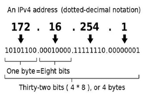
После того, как мы определились c тем, что такое IPv6 и IPv4, остановимся на вопросе «какова разница между IPv6 и IPv4?». De facto, IP-адрес являет собой двоичное число, но он также может быть записан в более удобном для человека формате. Например, 32-битный числовой адрес, используемый в IPv4, может быть оформлен в десятичной системе 4 цифрами, причём каждое цифра может иметь значение от 0 до 255. Например, это могут быть цифры 172.16.254.1.
Адреса протокола IPv6 являются 128-битными, и оформлены в шестнадцатеричной системе. К примеру, адрес в IPv6 может быть записан как 3ffe:1904:4546:3:201:f8ff:fe22:68cf.

Настройка IPv6 на Windows 7 (видео)
Выше мной были рассмотрены IPV6 и IPV4, мы узнали что это такое, обозначена специфика данных протоколов и описаны преимущества протокола IPv6 над IPv4. Несмотря на очевидный характер данных преимуществ, внедрение IPv6 идёт достаточно неспешно, множество специалистов фиксируют различные баги и проблемы в работе шестой версии протокола. Но в обозримом будущем, volens-nolens, более старый IPv4 уступит своё доминирующее положение более модерному, оптимальному и продвинутому протоколу IPv6. Эволюцию не остановить.
Packet Forwarding and Routing on IPv4 Networks
This section contains procedures and examples that show how to configure forwarding and routing for routers and hosts on IPv4 networks.
Packet forwarding is the basic method for sharing information across systems on a network. Packets are transferred between a source interface and a destination interface, usually on two different systems. When you issue a command or send a message to a nonlocal interface, your system forwards those packets onto the local network. The interface with the destination IP address that is specified in the packet headers then retrieves the packets from the local network. If the destination address is not on the local network, the packets are then forwarded to the next adjacent network, or hop. By default, packet forwarding is automatically configured when you install the Solaris OS.
Routing is the process by which systems decide where to send a packet. Routing protocols on a system “discover” the other systems on the local network. When the source system and the destination system are on the same local network, the path that packets travel between them is called a direct route. If a packet must travel at least one hop beyond its source system, the path between the source system and destination system is called an indirect route. The routing protocols learn the path to a destination interface and retain data about known routes in the system’s routing table.
Routers are specially configured systems with multiple physical interfaces that connect the router to more than one local network. Therefore, the router can forward packets beyond the home LAN, regardless of whether the router runs a routing protocol. For more information about how routers forward packets, refer to Planning for Routers on Your Network.
Routing protocols handle routing activity on a system and, by exchanging routing information with other hosts, maintain known routes to remote networks. Both routers and hosts can run routing protocols. The routing protocols on the host communicate with routing daemons on other routers and hosts. These protocols assist the host in determining where to forward packets. When network interfaces are enabled, the system automatically communicates with the routing daemons. These daemons monitor routers on the network and advertise the routers’ addresses to the hosts on the local network. Some routing protocols, though not all, also maintain statistics that you can use to measure routing performance. Unlike packet forwarding, you must explicitly configure routing on a Solaris system.
This section contains tasks for administering packet forwarding and routing on IPv4 routers and hosts. For information about routing on an IPv6-enabled network, refer to Configuring an IPv6 Router.
Routing Protocols Supported by the Solaris OS
Routing protocols are classified as interior gateway protocols (IGPs), exterior gateway protocols (EGPs), or a combination of both. Interior gateway protocols exchange routing information between routers on networks under common administrative control. In the network topology shown in Figure 5–3, the routers run an IGP for exchanging routing information. Exterior gateway protocols enable the router that connects the local internetwork to an external network to exchange information with another router on the external network. For example, the router that connects a corporate network to an ISP runs an EGP to exchange routing information with its router counterpart at the ISP. Border Gateway Protocol (BGP) is a popular EGP that is used for carrying routing information between different organizations and IGPs.
The following table provides information about the Solaris routing protocols and the location of each protocol’s associated documentation.
4. Thomson TCW770 EuroDOCSIS3.0 Wifi роутер
 Merdue (14 июня 2015 — 14:28) писал:
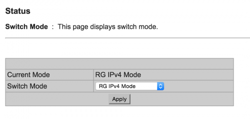
оставить RG4 как и установлено по-умолчанию. для пользователя разницы никакой
ИванЧернов (12 июня 2015 — 19:24) писал:
скриншоты настроек в студию
ИванЧернов (12 июня 2015 — 19:24) писал:
snike (13 июня 2015 — 14:34) писал:
#4645 ИванЧернов
Streamer (15 июня 2015 — 11:13) писал:
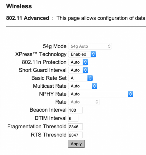
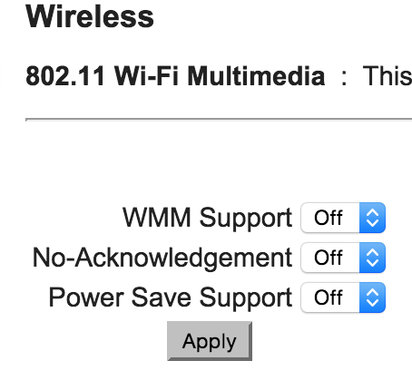
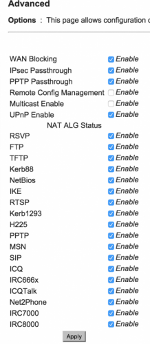
Заскриншотил основные экраны с ключевыми настройками. Что-то еще нужно?
Тему прочитал, все что там описано проделал, изменений нет. Все так же раз в 15 минут стабильно отрубается инет ((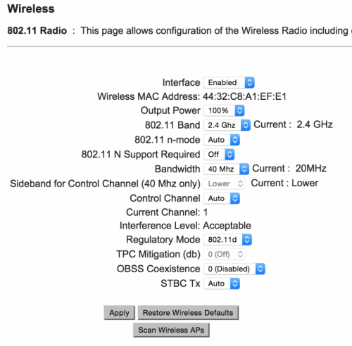
Streamer (15 июня 2015 — 11:13) писал:
скриншоты настроек в студию
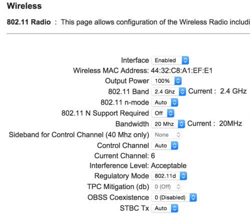
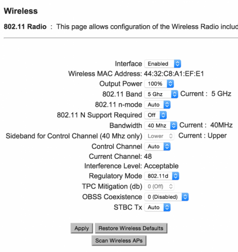
Грешил на загруженность канала на 2,4GHz, но ситуация не меняется и для 5GHz. Инет одинаково отваливается стабильно раз в 15 минут.
#4646 Streamer
ИванЧернов (15 июня 2015 — 15:56) писал:
что именно вы проделали, вот тут например рекомендуют патч на ядро MACOSx наложить — http://www.hub.ru/wiki/Apple
ИванЧернов (15 июня 2015 — 15:56) писал:
#4647 ИванЧернов
Streamer (15 июня 2015 — 15:58) писал:
Посмотрел какой региональный код у роутера — EU.
Проверил лог последних срабатываний 802.11d — все каналы были доступны, тем не менее интернет отваливался.
Также еще раз попробовал работу в диапазоне 2,4GHz, где, как я понял, эта проблема вообще неактуальна — симптомы те же.
А вот то что интернет у меня отваливается ровно раз в 15 минут это ни на какие мысли не наталкивает? Что может с такой периодичностью меняться в настройках роутера?
#4648 Streamer
ИванЧернов (15 июня 2015 — 16:06) писал:
ИванЧернов (15 июня 2015 — 16:06) писал:
пока нет. предлагаю попробовать по кабелю подключиться и посмотреть будут ли 15мин дисконнекты
-
.
- Перейдите в Настройки > Wi-Fi и найдите ту сеть Wi-Fi, к которой подключено устройство.
- Затем нажмите
 и Забыть эту сеть.
 - Попробуйте еще раз подключиться к нужной сети Wi-Fi.
Примечание. Если для подключения к сети Wi-Fi используется пароль, его понадобится ввести повторно.
#4649 ИванЧернов
Streamer (15 июня 2015 — 16:16) писал:
пока нет. предлагаю попробовать по кабелю подключиться и посмотреть будут ли 15мин дисконнекты
-
.
- Перейдите в Настройки > Wi-Fi и найдите ту сеть Wi-Fi, к которой подключено устройство.
- Затем нажмите и Забыть эту сеть.
- Попробуйте еще раз подключиться к нужной сети Wi-Fi.
Примечание. Если для подключения к сети Wi-Fi используется пароль, его понадобится ввести повторно.
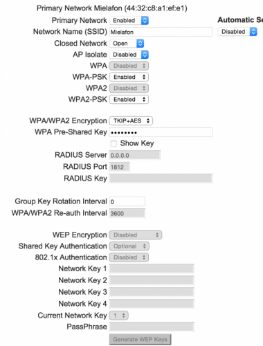
попробуйте оставить только WPA2-PSK и AES и ControlChannel выставить на фиксированный канал (посмотрите предварительно какие более свободны)
это сделал — нет эффекта
а также выполнить рекомендации с сайта тех. поддержки apple
сделал — аналогично
попробовать по кабелю подключиться и посмотреть будут ли 15мин дисконнекты
нет возможности, чтобы это попробовать нужен дорогостоящий переходник, в новом макбуке нет ethernet входа
что характерно, компьютер работает с офисным вайфаем и да и со всеми другими без таких проблем, так что все же проблема в роутере (
причем началось это пару недель назад, до этого ничего подобного не было и в помине.
если в ближайшее время проблема не решится придется менять провайдера (
#4650 Streamer
ИванЧернов (15 июня 2015 — 17:01) писал:
попробуйте оставить только WPA2-PSK и AES и ControlChannel выставить на фиксированный канал (посмотрите предварительно какие более свободны)
это сделал — нет эффекта
а также выполнить рекомендации с сайта тех. поддержки apple
сделал — аналогично
попробовать по кабелю подключиться и посмотреть будут ли 15мин дисконнекты
нет возможности, чтобы это попробовать нужен дорогостоящий переходник, в новом макбуке нет ethernet входа
что характерно, компьютер работает с офисным вайфаем и да и со всеми другими без таких проблем, так что все же проблема в роутере (
причем началось это пару недель назад, до этого ничего подобного не было и в помине.
если в ближайшее время проблема не решится придется менять провайдера (
#4651 ИванЧернов
Streamer (15 июня 2015 — 17:15) писал:
все только apple к сожалению
подключен в сетевой фильтр, попробовать напрямую?
Streamer (15 июня 2015 — 17:15) писал:
#4652 Streamer
ИванЧернов (15 июня 2015 — 17:35) писал:
прошивка последняя из имеющихся, STB06.07.04
посмотреть на закладке Software
ИванЧернов (15 июня 2015 — 17:35) писал:
#4653 ИванЧернов
Streamer (15 июня 2015 — 18:04) писал:
прошивка последняя из имеющихся, STB06.07.04
посмотреть на закладке Software
#4654 Streamer
ИванЧернов (15 июня 2015 — 20:14) писал:
#4655 ИванЧернов
Streamer (15 июня 2015 — 20:25) писал:
#4656 Streamer
ИванЧернов (15 июня 2015 — 20:43) писал:
#4657 ИванЧернов
Streamer (15 июня 2015 — 21:01) писал:
#4658 snike
Streamer (15 июня 2015 — 11:13) писал:
#4659 Streamer
snike (15 июня 2015 — 22:12) писал:
#4660 snike
Streamer (16 июня 2015 — 10:13) писал:
#4661 Streamer
snike (16 июня 2015 — 23:36) писал:
если нет аттенюатора на 3db то да. номер договора укажите в профиле
ИванЧернов (15 июня 2015 — 21:50) писал:
#4662 ИванЧернов
ИванЧернов (15 июня 2015 — 21:50) писал:
поменял номер сети — все то же
потом отключил DHCP сервер и стало все ОК!!!! Ура!! )))
Вот только вопрос — почему это происходило и можно ли как-то настроить?
все же не очень удобно вручную вбивать для каждого нового устройства IP и DNS
может поиграться с Lease time? оно вообще в чем выставлено? похоже что его система считает равным 15 минутам как раз ))

Сообщение отредактировал ИванЧернов: 17 июня 2015 — 17:55
- Страниц
- 234
Количество пользователей, читающих эту тему: 3
0 пользователей, 3 гостей, 0 анонимных

- Изменить стиль
- Новый год
- Akado+snow
- Akado
- Akado Mobile
- Green
- Форумы
- Галерея
- Отметить все как прочтенное