Acpi sleep state, S1 only (cpu stop clock), 3 trusted computing – ADLINK cPCI-6520 User Manual

Select the highest ACPI sleep state the system will enter, when
the SUSPEND button is pressed. Set this value to S1 only, Sus-
pend Disable.
S1 only (CPU Stop Clock)
Power On Suspend — Under this setting the CPU is not execut-
ing instructions, all power resources that supply system level
reference of S0 are off, system memory context is maintained,
devices that reference power resources that are on are on, and
devices that can wake-up the system can cause the CPU to
continue to execute from where it left off.
Trusted Computing
Trusted Computing is an industry standard to make personal com-
puters more secure through a dedicated hardware chip, called a
Trusted Platform Module (TPM). This option allows you to enable
or disable the TPM support.
Частые вопросы по китайским материнским платам lga 2011 (huanan, yanwei и другие)
Как китайские материнки в целом?
За последние годы качество китайских комплектующих сильно выросло. Так, платы с брендом huanan сейчас по качеству примерно на уровне обычных бюджетных брендовых плат. Тоже можно сказать и про серии плат x79z, e5 ver 3.2 и некоторые другие.
Более дешевые noname платы, в изобилии встречающиеся на али и таобао выполнены похуже, явно заметна экономия на элементах. Шансы брака у них выше, вероятность появления модифицированного биоса — меньше. Тем не менее, при ограниченном бюджете можно использовать и их, на свой страх и риск, конечно.
Какую плату лучше выбрать?
Не могу зайти в биос. Клавиши ESC, Delete, F2 не помогают.
Попробуйте комбинацию Space + Esc.
Зажать произвольную клавишу (например пробел), а потом нажимать f2 или esc. Смысл в том, что комбинации биоса, загрузчиков и т.д. не понимают кнопки пока не зажать произвольную клавишу. Почему такое происходит и в каких случаях проявляется, до конца не понятно.
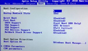
Данную проблему можно решить окончательно, в настройках BIOS, по следующей схеме:
1) Попадаем в BIOS по инструкции выше.
2) Переходим в раздел Boot.
3) В строке Setup Prompt Timeout прописываем 5 или более (по дефолту прописано 1)
У меня не работает сон, кулеры продолжают крутиться, можно это исправить?
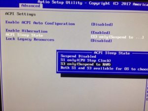
Зависит от модели платы и версии биоса. Можно попробовать следующее (работает на
Huanan X79 New
): в БИОСе, во вкладке
Advanced
->
ACPI Settings
параметр
ACPI Sleep State
поменять с
S1 only (CPU Stop Clock)
(по-умолчанию) на
S3 only (Suspend to RAM)
.
Другие варианты решения проблемы смотрите
здесь
.
Двойной старт. Компьютер сначала выключается и потом включается. Можно исправить?
Есть несколько советов, которые могут помочь.
- Обновите версию bios
- Изменените в биосе «energy performance» режимов с «performance» на «balanced performance» и на оборот
- Попробуйте отключить все usb устройства, поменять порты или подключить все через usb 3.0
У меня не работает turbo boost. Как включить?
В биосе включить пункт
Energy Performance
в режим по умолчанию (
Balanced Performance
), в windows активировать профиль
высокая производительность
.
У меня процессор с разблокированным множителем. Как его разогнать? Какие параметры менять в биосе?
Пытаюсь сделать дамп биоса через afudos. Сливаю несколько раз дампы, а они разные.
Снимайте/шейте дамп версией афудоса под aptio4 а не под amibios8.
Как сделать загрузку с NVMe накопителя?
В биосе Boot — Launch CSM — Disabled. Перед этим проверить поддержку UEFI видеокартой. Делаем флешку в руфусе — GPT.
Далее следуем инструкциям из п.4
. Биос шить не нужно.
Иными словами: видеокарта должна поддерживать UEFI, система должна быть установлена на GPT, а не MBR, а в биосе нужно выбрать «UEFI only» в пункте «Launch CSM» вкладки Boot .
У меня плата на чипсете c602. Хочу включить и настроить raid. Как это сделать?
Для активации Raid, в Bios в свойствах Sata контроллера нужно включить режим raid. Чтобы зайти в настройки Raid или создать новый массив — при включении компьютера удерживать CTRL+l. Обновление bios, сброс настроек не вносят никаких изменений в Raid массив.
Нужно иметь ввиду, что установщик Windows 10 не имеет нужных драйверов, поэтому их нужно заранее переписать на флешку. Скачать можно
здесь
.
Также, во многих торрент раздачах Windows 10 поддержка raid вырезана.
Как сбросить биос?
Обесточить материнскую плату и вынуть батарейку минут на 10 (для надежности). Можно также сбросить перемычкой:
The motherboard 24P power supply and CPU power supply off, then put the battery on the motherboard to pull up, and then put on the motherboard black jumper originally in the 2.3 pin, 1.2 pin pull up the jump to the left, for 30 minutes, then pull on the black jumper back to the original 2.3 pin, connected in turn to see.
После прошивки биоса плата запускается на пару секунд, выключается и включается снова, но сигнала на мониторе нет, молчит спикер нет посткодов
Подобное поведение характерно при прошивке несовместимого биоса (от другой ревизии или вовсе от другой платы). Как правило выход один — прошивка родного дампа программатором, но сначала попробуйте сбросить биос и запуститься в минимальной конфигурации.
После прошивки модифицированного биоса стала долго грузиться Windows
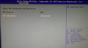
Попробуйте отключить Intel ME. Сделать это можно двумя способами:
- Заходим в диспетчер устройств, находим там
Intel Management Engine Interface
и отключаем его. - Заходим в биос и в разделе чипсета переключаем параметр
ME Subsystem
в
Disabled
.
Не работает перестала работать usb клавиатура в биосе
Подобный казус в иногда может произойти после прошивки модифицированного или портированного с другой платы биоса.
- Попробуйте переключить клавиатуру из порта usb 3.0 в usb 2.0 (или наоборот)
- В настройках USB устройств в биосе проверьте, что параметр XHCI Hand-off установлен в положение Enabled, а параметр EHCI Hand-off — в положение Disabled. После сохранения настроек проверьте работоспособность клавиатуры во всех портах.
В крайнем случае — придется найти ps/2 клавиатуру. В некоторых случаях может помочь сброс биоса.
Не получается настроить smartfan кулер всегда работает на полную
В некоторых версиях bios датчик температуры может «врать» на 20 градусов. То есть, при установке определенного PWM — % (проценты от максимальных оборотов кулера) на 50 градусов, по факту смартфан будет считать за 70 градусов.
Проблемы при старте
При старте компьютера материнка издает трель разных писков, но запускается нормально. Так и должно быть?
Да, это штатное поведение платы. Количество пищания зависит от количества/конфигурации подключеных устройств. Если Вас раздражает писк — отключайте динамик.
Система стартует через раз (все вентиляторы вращаются, но черный экран). Но если запустилась, то работает стабильно. В чем проблема?
Возможно проблема
«совместимости»
БП и материнки. Проверьте напряжение в момент такого вот не старта на контакте блока питания «Power Good» (8 нога в 24 пиновом ATX разъеме, обычно имеет цвет серый). На этой ноге должно быть от 3 до 6 вольт, обычно 5 вольт. Если там менее 3-х вольт, то система не стартанет.
Периодически ловлю синие экраны. В чем проблема?
Если разгонялся процессор или память — снизьте или совсем уберите разгон.
Если операционка не переустанавливалась после смены платформы — лучше сделать это.
Также стоит проверить южный мост — если он слишком горячий — это может вызвать синие экраны. Попробуйте перемазать пасту или заменить радиатор южного моста.
Собрал систему, включаю — не запускается. Что делать?
Разобрать обратно и проверить с минимально рабочей комплектацией ( процессор, 1 планка памяти, видеокарта). Если запустилась — добавлять комплектующие по одному, чтобы найти проблемный компонент (часто это оперативка).
Можно также сбросить биос (как это сделать см. выше).
Если ничего не помогло — аккуратно протереть спиртом все контакты у процессора и оперативки. Внимательно осмотреть сокет на предмет поврежденных/гнутых/почерневших ножек.
Другие проблемы
Свистят или шумят дроссели на плате.
Первым делом убедитесь, что звук издает именно плата, а не, например, видеокарта.
Если в шуме виновата материнка, то можно попробовать 2 способа
из видео
:
- В биосе находим меню CPU Power Management Configuretion, в нем переключаем значение Power Technology в Custom. В открывшемся меню переводим параметр CPU C6 Report в положение Disabled. Сохраняемся, перезагружаем систему и проверяем эффект.
- Скачиваем программа ThrottleSTOP. Запускаем, снимаем галочку с C1E, проверяем эффект. Если подействовало — можно добавить программу в автозагрузку.
При оценке системы на win7x64 вылетает ошибка на тесте памяти.
Cтавите заплатку Windows6.1-KB2619497-v2-x64 и тогда тест пройдёт без ошибок.
PCI-E показывает режим 1.0/2.0, где обещанные 3.0 ?
В режиме простоя плата снижает частоту. Запустите любую 3Д нагрузку (бенчмарк в оконном режиме) и смотрите показатели PCI-E.
По прежнему показывает PCI-E 2.0
Поможет рецепт от nvidia
Geforce Gen3 Support On X79 Platform
или скачать
отсюда файлик
(в самом низу). Обязательно запустить с правами администратора и перезагрузить компьютер!
Проблема с отображением диспетчера Realtek HD (не загружается в трей, отдельно тоже не запускается)
Есть глюки на версии драйвера R2.82. Откатитесь на более раннюю — R2.81.
Нет звука на передней панели
Все китайские платы идут с чипами производства Realtek (ALC 662883887888892), поэтому инструкция должна быть актуальна для всех моделей.
Установите версию Realtek High Definition Audio Drivers 2.81 (не 2.82), после перезагрузки проверьте наличие в трее значка Realtek.
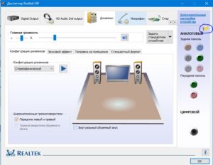
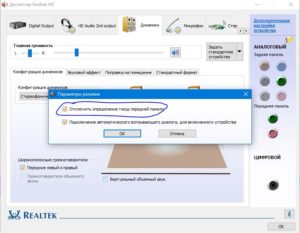
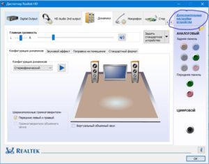
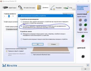
Затем заходим в диспетчер Realtek и нажимаем на папочку “Параметры разъема”. В открывшемся окне устанавливаем чек-бокс на пункте “Отключить определение гнезд передней панели”. Затем идем в «дополнительные настройки устройства» и устанавливаем галочку «Настроить переднее и заднее выходные устройства для одновременного воспроизведения двух различных звуковых сигналов».
Просаживается скорость записи или чтения из памяти. Как исправить?
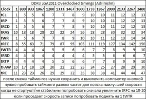
Если плата поддерживает управление таймингами — подберите наиболее удачные для вашей памяти. Данные можно брать из таблички:
Затем проверьте стабильность через
TestMem5
.
Стало лучше, но просадка все равно осталась.
Попробуйте после изменения таймингов полностью выключить компьютер и включить заново. Также можно попробовать метод из
этого видео
.
BIOS: настройка режима расширенного конфигурирования и управления питанием ACPI
BIOS
Здравствуйте, уважаемые читатели блога Help начинающему пользователю компьютера. В данной статье мы рассмотрим опции БИОС для настройки режима расширенного конфигурирования и управления питанием ACPI .
В качестве ликбеза. Режим расширенного управления питания ACPI ( Advanced Configuration and Power Interface ) реализует управление энергосберегающими функциями ПК:
6. BIOS Setup Utility
Power on the computer and press Delete during the beginning of the boot sequence to enter the BIOS Setup Utility. If the entry point has passed, restart the system and try again.
6.2. Control Keys
| Key | Function |
|---|---|
| Up | Move up one row |
| Down | Move down one row |
| Left | Move to the left in the navigation bar |
| Right | Move to the right in the navigation bar |
| Enter | Access the highlighted item / Select the item |
| Esc | Jumps to the Exit screen or returns to the previous screen |
| + [1] | Increase the numeric value |
| — [1] | Decrease the numeric value |
| F1 | General help [2] |
| F2 | Previous value |
| F3 | Load optimized defaults |
| F4 | Save all the changes and exit |
| [1] | (1, 2) Must be pressed using the 10-key pad. |
| [2] | The General help contents are only for the Status Page and Option Page setup menus. |
6.3. Getting Help
The BIOS Setup Utility provides a General Help screen. This screen can be accessed at any time by pressing F1. The help screen displays the keys for using and navigating the BIOS Setup Utility. Press Esc to exit the help screen.
6.4. System Overview
The System Overview screen is the default screen that is shown when the BIOS Setup Utility is launched. This screen can be accessed by traversing the navigation bar to the “Main” label.
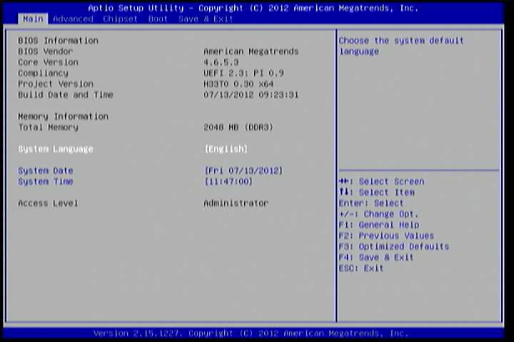
Figure 1: Illustration of the Main menu screen
6.4.1. BIOS Information
The content in this section of the screen shows the information about the vendor, the Core version, UEFI specification version, the project version and date & time of the project build.
6.4.2. Memory Information
This section shows the amount of memory that is installed on the hardware platform.
6.4.3. System Language
This option allows the user to configure the language that the user wants to use.
6.4.4. System Date
This section shows the current system date. Press Tab to traverse right and Shift+Tab to traverse left through the month, day, and year segments. The + and — keys on the number pad can be used to change the values. The weekday name is automatically updated when the date is altered. The date format is [Weekday, Month, Day, Year].
6.4.5. System Time
This section shows the current system time. Press Tab to traverse right and Shift+Tab to traverse left through the hour, minute, and second segments. The + and — keys on the number pad can be used to change the values. The time format is [Hour : Minute : Second].
6.5. Advanced Settings
The Advanced Settings screen shows a list of categories that can provide access to a sub-screen. Sub-screen links can be identified by the preceding right-facing arrowhead.
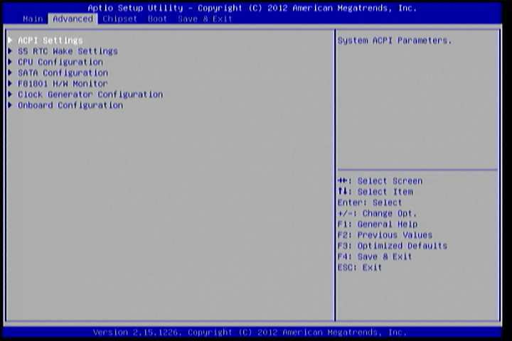
Figure 2: Illustration of the Advanced Settings screen
The Advanced Settings screen contains the following links:
- ACPI Settings
- S5 RTC Wake Settings
- CPU Configuration
- SATA Configuration
- F81801 H/W Monitor
- Clock Generator Configuration
- Onboard Configuration
6.5.1. ACPI Settings
ACPI grants the operating system direct control over system power management. The ACPI Configuration screen can be used to set a number of power management related functions.
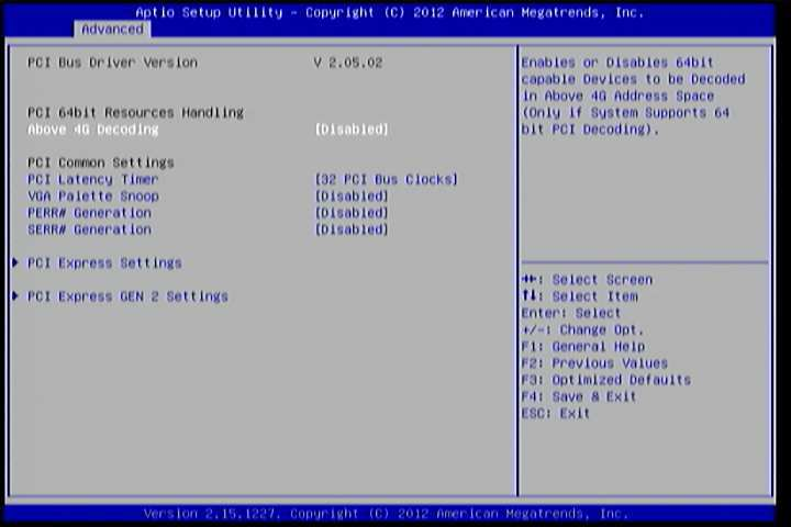
Figure 3: Illustration of the ACPI Settings screen
6.5.1.1. Enable Hibernation
Enable/disable system ability to Hibernate.
6.5.1.2. ACPI Sleep State
Select the highest ACPI sleep state the system will enter when the SUSPEND button is selected. Available options are:
- Suspend Disabled
- S1(CPU Stop Clock)
- S3 (Suspend to RAM)
- Both S1 and S3 available for OS to choose.
6.5.2. S5 RTC Wake Settings
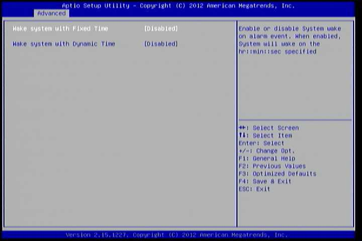
Figure 4: Illustration of the S5 RTC Wake Settings screen
6.5.2.1. Wake system with Fixed Time
Enable or disable system wake on alarm event. When enabled, system will wake on the hr:min:sec specified.
6.5.2.2. Wake system with Dynamic Time
Enable or disable Wake system with Dynamic Time.
6.5.3. CPU Configuration
The CPU Configuration screen shows detailed information about the built-in processor. In addition to the processor information, the thermal controls can be set.
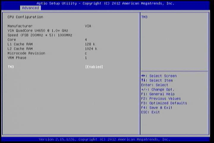
Figure 5: Illustration of CPU Configuration screen
6.5.3.1. TM3
The TM3 Function has two settings: Disabled and Enabled. When the setting is changed to “Disabled”, the CPU’s built-in thermal sensor will not function. When the setting is changed to “Enabled”, the thermal sensor will automatically adjust the CPU ratio and V CORE to prevent the CPU from overheating.
6.5.4. SATA Configuration
The SATA Configuration screen allows the user to view and configure the settings of the SATA configuration settings.
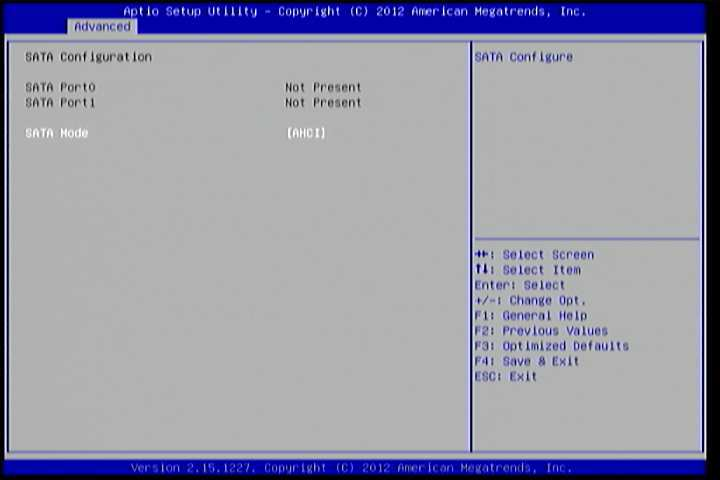
Figure 6: Illustration of SATA Configuration screen
6.5.4.1. SATA Mode
This option allows the user to manually configure SATA controller for a particular mode.
- IDE Mode: Set this value to change the SATA to IDE mode.
- AHCI Mode: Set this value to change the SATA to AHCI mode.
6.5.5. PC Health Status
The PC Health Status screen has no editable fields. The system temperature is taken from an optional sensor that is connected to the J5 pin header.
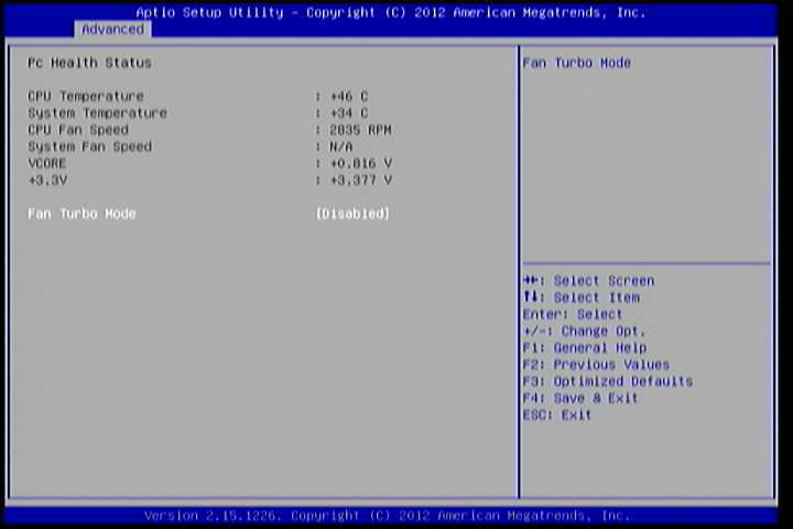
Figure 7: Illustration of PC Health Status screen
6.5.5.1. Fan Turbo Mode
This option allows the user to Enable or Disable Fan Turbo Mode.
6.5.6. Clock Generator Configuration
The Clock Generator Configuration screen enables access to the Spread Spectrum Setting feature.
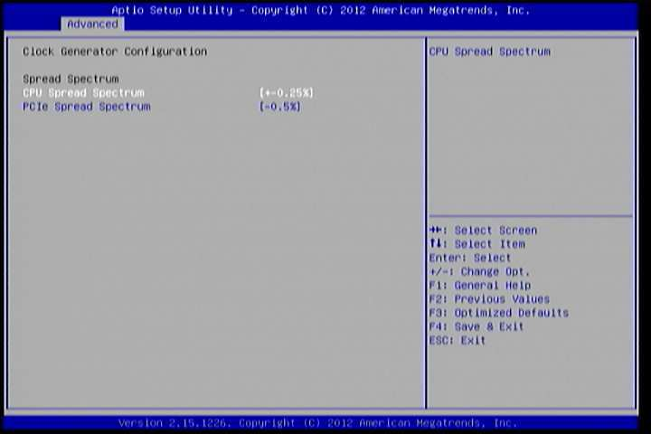
Figure 8: Illustration of Clock Generator Configuration screen
6.5.6.1. CPU Spread Spectrum
The Spread Spectrum Setting feature enables the BIOS to modulate the clock frequencies originating from the mainboard. The settings are in percentages of modulation. Higher percentages result in greater modulation of clock frequencies. This feature has 3 options: Disable, +-0.25% and -0.5%.
6.5.6.2. PCIe Spread Spectrum
Select PCIe Spread Spectrum. This feature has 2 options: Disable and -0.5%.
6.5.7. OnBoard Device Configuration
The OnBoard Device Configuration screen has the following features.
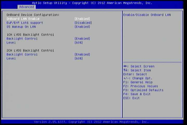
Figure 9: Illustration of OnBoard Device Configuration screen
6.5.7.1. OnBoard LAN Enable
The OnBoard LAN Enable feature determines whether the onboard LAN controller will be used or not.
6.5.7.2. EuP/ErP Lot6 support
The EuP/ErP Lot6 Support feature enables the BIOS to reduce the power draw to less than 1W when the system is in standby mode. This feature has two options: enabled and disabled.
6.5.7.3. S5 Wakeup On LAN
The S5 Wakeup On LAN feature enables the BIOS to allow remote wake-up from the S5 power off state through the PCI bus.
6.5.7.4. 1CH LVDS Backlight Control
Backlight Control
The Backlight Control feature control by VX11H enables the user to control the brightness of the 1CH LVDS backlight. This feature has six options.
Level 0%, 20%, 40%, 60%, 80% and 100%.
6.5.7.5. 2CH LVDS Backlight Control
Backlight Control
The Backlight Control feature control by VX11H enables the user to control the brightness of the 2CH LVDS backlight. This feature has six options.
Level
0%, 20%, 40%, 60%, 80% and 100%.
6.6. Chipset Settings
The Chipset Settings screen shows a list of categories that can provide access to a sub-screen. Sub-screen links can be identified by the preceding right- facing arrowhead.
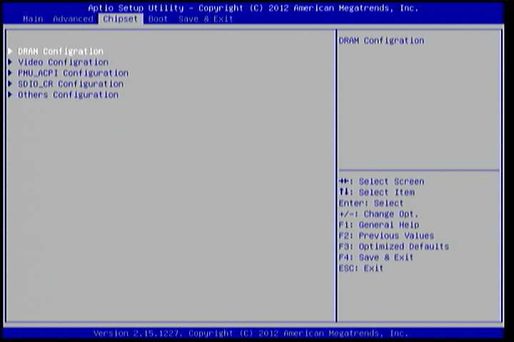
Figure 10: Illustration of Chipset Settings screen
The Chipset Settings screen contains the following links:
- DRAM Configuration
- Video Configuration
- PMU-ACPI Configuration
- SDIO_CR Configuration
- Others Configuration
6.6.1. DRAM Configuration
The DRAM Configuration screen has two features for controlling the system DRAM. All other DRAM features are automated and cannot be accessed.
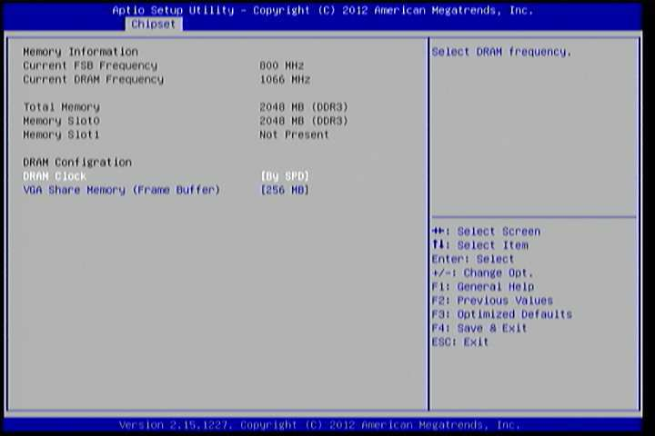
Figure 11: Illustration of DRAM Configuration screen
6.6.1.1. DRAM Clock
The DRAM Clock option enables the user to determine how the BIOS handles the memory clock frequency. The memory clock can either be dynamic or static. This feature has eleven options.
By SPD
By SPD option enables the BIOS to select a compatible clock frequency for the installed memory.
400 MHz
The 400 MHz option forces the BIOS to be fixed at 800 MHz for DDR3 memory modules.
533 MHz
The 533 MHz option forces the BIOS to be fixed at 1066 MHz for DDR3 memory modules.
566 MHz
The 566 MHz option forces the BIOS to be fixed at 1132 MHz for DDR3 memory modules.
600 MHz
The 600 MHz option forces the BIOS to be fixed at 1200 MHz for DDR3 memory modules.
633 MHz
The 633 MHz option forces the BIOS to be fixed at 1266 MHz for DDR3 memory modules.
667 MHz
The 667 MHz option forces the BIOS to be fixed at 1334 MHz for DDR3 memory modules.
6.6.1.2. VGA Share Memory (Frame Buffer)
The VGA Share Memory feature enables the user to choose the amount of the system memory to reserve for use by the integrated graphics controller. The selections of memory amount that can be reserved are 256MB and 512MB.
6.6.2. Video Configuration
The Video Configuration screen has features for controlling the integrated graphics controller in the VX11H chipset.
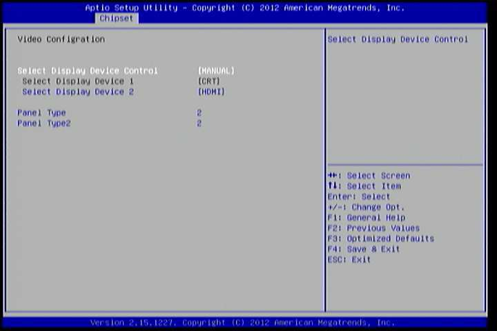
Figure 12: Illustration of Video Configuration screen
6.6.2.1. Select Display Device Control
Available selections are: Auto and Manual.
6.6.2.2. Select Display Device 1 and 2
The Select Display Device feature enables the user to choose a specific display interface. This feature has four options: CRT, LCD, LCD2 and HDMI. If both Select Display Device 1 and Select Display Device 2 are set to the same interface, then any display device connected to the other interface will not function. For example, if both Select Display 1 and 2 are set to CRT, then no data will be sent to the HDMI, LCD and LCD2 port.
6.6.2.3. Panel Type
The Panel Type feature enables the user to specify the resolution of the display being used with the system. The panel types are predefined in the VGA VBIOS.
| Panel Type | Resolution | Panel Type | Resolution |
|---|---|---|---|
| 00 | 640 x 480 | 08 | 800 x 480 |
| 01 | 800 x 600 | 09 | 1024 x 600 |
| 02 | 1024 x 768 | 10 | 1366 x 768 |
| 03 | 1280 x 768 | 11 | 1600 x 1200 |
| 04 | 1280 x 1024 | 12 | 1680 x 1050 |
| 05 | 1400 x 1050 | 13 | 1920 x 1200 |
| 06 | 1440 x 900 | 14 | 1920 x 1080 |
| 07 | 1280 x 800 | 15 | 1024 x 576 |
6.6.2.4. Panel Type2
The Panel Type feature enables the user to specify the resolution of display 2 being used with the system. The panel types are predefined in the VGA VBIOS.
| Panel Type | Resolution | Panel Type | Resolution |
|---|---|---|---|
| 00 | 640 x 480 | 08 | 800 x 480 |
| 01 | 800 x 600 | 09 | 1024 x 600 |
| 02 | 1024 x 768 | 10 | 1366 x 768 |
| 03 | 1280 x 768 | 11 | 1600 x 1200 |
| 04 | 1280 x 1024 | 12 | 1680 x 1050 |
| 05 | 1400 x 1050 | 13 | 1920 x 1200 |
| 06 | 1440 x 900 | 14 | 1920 x 1080 |
| 07 | 1280 x 800 | 15 | 1024 x 576 |
6.6.3. PMU_ACPI Configuration
The PMU_ACPI Configuration screen can be used to set a number of power management related functions.
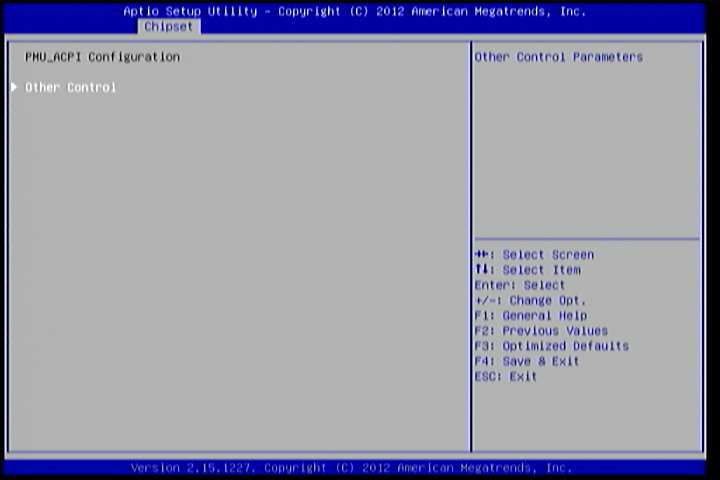
Figure 13: Illustration of PMU_ACPI Configuration screen
6.6.3.1. Other Control
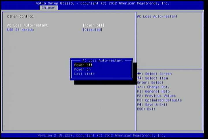
Figure 14: Illustration of Other Control screen
AC Loss Auto-restart
AC Loss Auto-restart defines how the system will respond after AC power has been interrupted while the system is on. There are three options.
The Power Off option keeps the system in an off state until the power button is pressed again.
The Power On option restarts the system when the power has returned.
The Last State option restores the system to its previous state when the power was interrupted.
USB S4 WakeUp
The USB S4 WakeUp enables the system to resume through the USB device port from S4 state. There are two options: “Enabled” or “Disabled”.
6.6.4. SDIO_CR Configuration
The SDIO_CR Configuration screen can be used to set SDIO_CR configuration parameters.
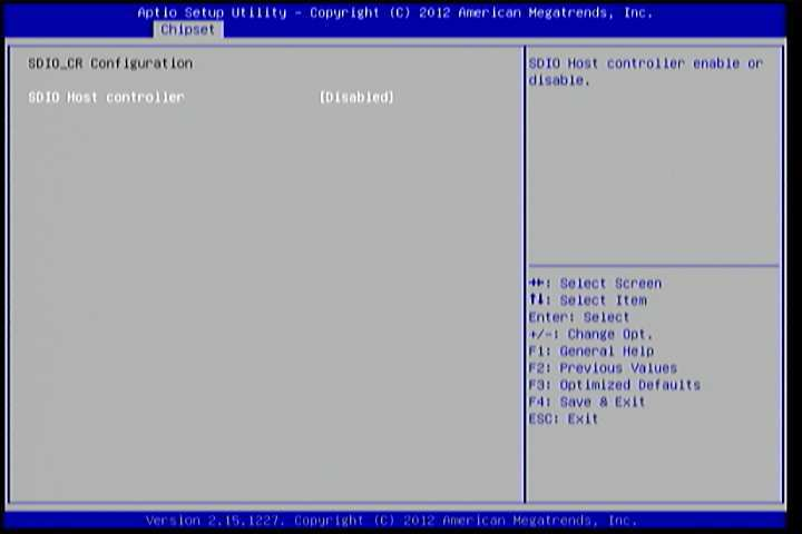
Figure 15: Illustration of SDIO_CR Configuration screen
6.6.4.1. SDIO Host Controller
Available selections are: Enabled and Disabled.
6.6.4.2. SDIO Specification Ver3.0 Support
Available selections are: Enabled and Disabled.
6.6.4.3. Voltage Support 1.8v
Available selections are: Enabled and Disabled.
6.6.4.4. High Speed Support
Available selections are: Enabled and Disabled.
6.6.4.5. Driver Type Select
Available selections are: Type A, Type B, Type C and Type D.
6.6.4.6. SDR50 Support
Available selections are: Enabled and Disabled.
6.6.4.7. SDR104 Support
Available selections are: Enabled and Disabled.
6.6.4.8. DDR50 Support
Available selections are: Enabled and Disabled.
6.6.4.9. SDR50 Tuning Enable
Available selections are: Enabled and Disabled.
6.6.4.10. Timer Count for Re-Tuning
Available selections are:
- 1 second
- 2 seconds
- 4 seconds
- 8 seconds
- 16 seconds
- 32 seconds
- 64 seconds
- 120 seconds
- 256 seconds
- 512 seconds
- 1024 seconds
- get information from other source
6.6.4.11. Card Reader Host Controller 0
Available selections are: Enabled and Disabled.
6.6.5. Others Configuration
The Others Configuration screen can be used to set Watchdog Timer Configuration and Keyboard/Mouse Wakeup Configuration.
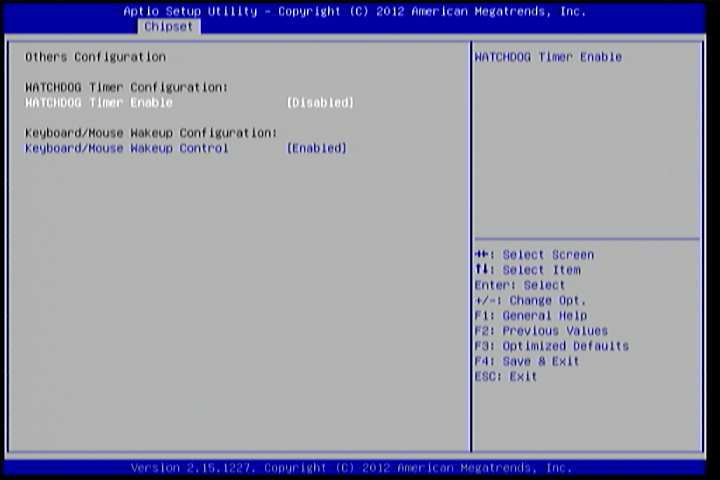
Figure 16: Illustration of Others Configuration screen
6.6.5.1. WATCHDOG Timer Enable
When this feature is enabled, an embedded timing device automatically prompts corrective action upon system malfunction detection.
6.6.5.2. Keyboard/Mouse Wakeup Control
When this feature is enabled, pressing any key of the keyboard or moving the mouse can wake up the system from suspend.
6.7. Boot Settings
The Boot Settings screen has a single link that goes to the Boot Configuration and Boot Option Priorities screens.
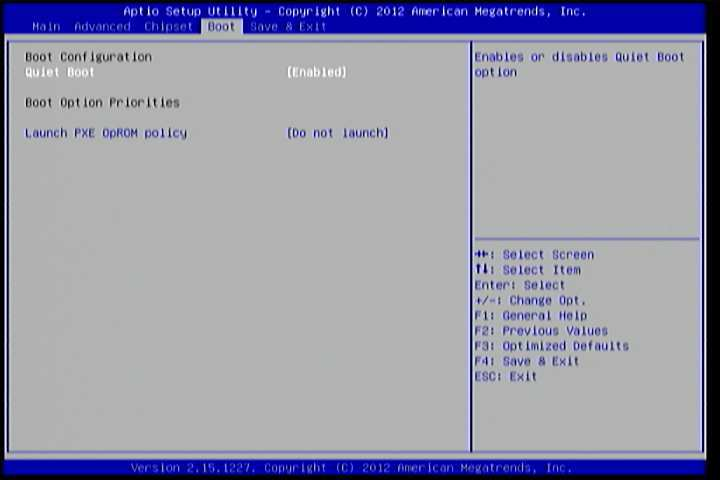
Figure 17: Illustration of Boot Settings screen
6.7.1. Boot Configuration
The Boot Settings Configuration screen has several features that can be run during the system boot sequence.
6.7.1.1. Quiet Boot
The Quiet Boot feature hides all of the Power-on Self Test (POST) messages during the boot sequence. Instead of the POST messages, the user will see an OEM logo. This feature has two options: enabled and disabled.
6.7.2. Boot Option Priorities
The Boot Option Priorities screen lists all bootable devices.
6.7.2.1. Launch PXE OpROM policy
Do not launch
Prevent the option for Legacy Network Device.
Legacy only
Allow the option for Legacy Network Device.
6.8. Save & Exit
The Save & Exit Configuration screen has the following features:
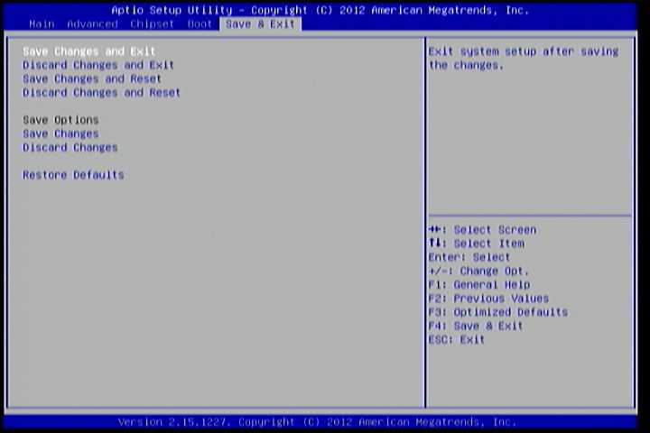
Figure 18: Illustration of Save & Exit screen
6.8.1. Save Changes and Exit
Save all changes to the BIOS and exit the BIOS Setup Utility. The “F10” hotkey can also be used to trigger this command.
6.8.2. Discard Changes and Exit
Exit the BIOS Setup Utility without saving any changes. The “Esc” hotkey can also be used to trigger this command.
6.8.3. Save Changes and Reset
Save all changes to the BIOS and reboot the system. The new system configuration parameters will take effect.
6.8.4. Discard Changes and Reset
This command reverts all changes to the settings that were in place when the BIOS Setup Utility was launched. The “F7” hotkey can also be used to trigger this command.
6.8.5. Save Options
Save Changes done so far to any of the setup options.
6.8.6. Save Changes
Save system configuration and continue. For some of the options it required to reset the system to take effect.